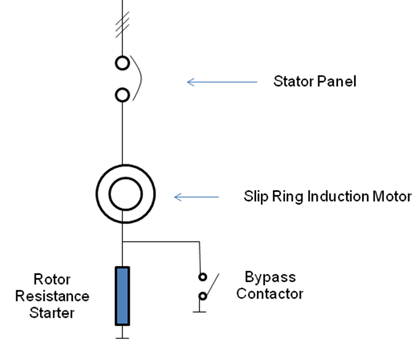
Generally, Slipring Induction Motors are used in applications that require high starting torque. This is achieved by connecting additional starting resistance in the rotor circuit. The resistance is reduced gradually in steps to increase motor speed while maintaining the required torque.
Slip Dependent Rotor Resistance Starters are designed with a lossy core and are based on rotor frequency dependent resistance design. This provides low starting current with automatic resistance reduction, which is inversely proportional to motor speed. As a result, the motor accelerates smoothly without electrical or mechanical jerks.
The starter is connected to the rotor terminals of the motor, limiting starting current while providing high starting torque. Motor acceleration is smooth and stepless due to automatic resistance variation. After reaching full speed, the rotor starter is cut out of the circuit using an inbuilt bypass contactor. During normal operation, the motor functions as a squirrel cage induction motor.